The planet rings need to be fixed to the tubes, which are in turn soldered to the driven planet gear. Ideally, the rings would be adjustable so the planets could be realigned on occasion. So instead of soldering the rings to the tubes a hub was designed that would be mounted to the tube with a set screw and fixed to the ring with three screws.
The hub is simply a 1/8" disk of 1" aluminum that has a hole sized to fit the particular planet's tube, three holes for attaching to the planet ring, and a cross hole for a set screw.
The hubs were cut from a 1" length of 1 1/4" round aluminum rod (cut on the bandsaw from a 6" length as that is what was on hand). The 1" length was long enough to hold in the three jaw chuck and allow for the manufacture of all four required hubs. After facing one end and reducing about 5/8" to 1" the first 1/16" was further reduced to 5/8". The part was then center drilled, drilled through and reamed to 3/16" fitting the smallest tube. The stepped disc was parted off at 1/8". This process was then repeated for the next three hubs with center holes of increasing size: 1/4", 5/16", and 3/8".
The hubs were marked at 120° increments and placed in vise with one mark aligned with the vee groove in the vise. The inside edge of the vise was found with the edge finder and the vise was moved in 3/16". A #43 drill (note: changed from diagram above) was used to drill through the disk followed by tapping 4-40. This was repeated for each of the other two 120° marks and for the other three hubs.
A hub was aligned in the milling vise. The center was aligned with the spindle by finding one edge of the hub. A 1/8" end mill was used to cut away part of the outer rim for the set screw. This was repeated on the other three hubs.
A hub was placed in a vise and the flat side was found and the table was dialed 1/16" to place spindle over center. A 1/8" drill bit was then placed in a chuck in the spindle and this was used to align the spindle with the groove made previously. A #43 drill bit was used to drill through for the tap. The hole was tapped 4-40 through to the center hole. A little cleanup with a reamer and a file produced the finished hub. Drilling and tapping was repeated on the remaining 3 hubs.
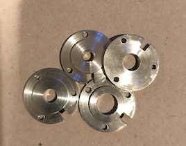
The completed ring hubs are shown in the following photo.
The hubs were attached to the rings by first carefully aligning the hub and ring (with the use of a tube in the center hole). One hole was marked, the ring and hub separated, and the marked point was drilled through with a #36 drill. A 4-40 screw through the new hole was used to hold the ring and hub together. A second hole was then marked in the ring, the ring/hub separated, and the marked spot was drilled through. Screwing the ring and hub together through the two holes led to the third hole in the correct spot. The 1/2" 4-40 button head screws were shortened to length and cleaned up prior to final assembly.